~How does the SB sensor measure printing pressure?~
This time, I will talk about the "SB sensor ADVANCE" (hereinafter referred to as "SB sensor") mechanism.
The SB sensor converts the electrical resistance of the sensor sheet into voltage with an AD converter. Then the voltage is further converted into a unitless digital value (RAW value).
The reason why we do this is that the sensor sheet has the property that the higher the printing pressure, the lower the resistance value. Therefore, an AD converter is used to convert the signal so that the higher the printing pressure, the larger the signal. If you use this value to draw a bar graph on your computer, the higher the printing pressure, the higher the bar graph will be, and you will be able to visually see the strength of the printing pressure as an increase or decrease in the bar graph.
The reason why we do this is that the sensor sheet has the property that the higher the printing pressure, the lower the resistance value. Therefore, an AD converter is used to convert the signal so that the higher the printing pressure, the larger the signal. If you use this value to draw a bar graph on your computer, the higher the printing pressure, the higher the bar graph will be, and you will be able to visually see the strength of the printing pressure as an increase or decrease in the bar graph.
Since the RAW value increases or decreases in proportion to the printing pressure, the RAW value can be converted to engineering units by measuring the RAW value when the standard printing pressure is applied to the sensor sheet. This is calibration. There are 7 channels of electrodes on the sensor sheet, and the characteristics of each channel vary slightly, so calibration is performed to correct the variation between channels. The SB sensor is calibrated by placing a weight of 0.4 kgf/cm on each channel.
Next, I will explain how the sensor sheet works.
The structure is a switch structure called a membrane switch. With a normal switch, pressing the electrode simply shorts the circuit and does not change the resistance value.
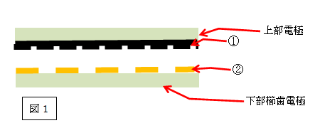
The upper electrode of the sensor sheet has special unevenness (Fig. 1-①) as shown in Fig. 1. In addition, a comb-shaped electrode (Fig. 1-②) is formed on the lower electrode. The AD converter sees the resistance value between the lower comb-teeth electrodes.When the printing pressure is zero, the upper and lower electrodes of the sensor sheet are separated as shown in Fig.1, and the resistance value between the lower comb-teeth electrodes at that time is ∞.
The upper electrode of the sensor sheet has special unevenness (Fig. 1-①) as shown in Fig. 1. In addition, a comb-shaped electrode (Fig. 1-②) is formed on the lower electrode. The AD converter sees the resistance value between the lower comb-teeth electrodes.When the printing pressure is zero, the upper and lower electrodes of the sensor sheet are separated as shown in Fig.1, and the resistance value between the lower comb-teeth electrodes at that time is ∞.

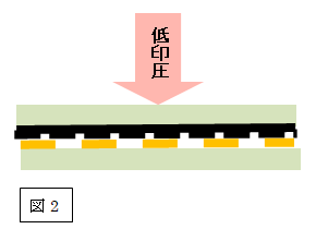
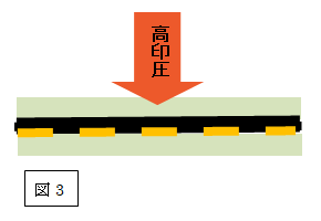
When the electrode is pushed with a squeegee, the upper electrode comes into contact with the lower comb-teeth electrode and shorts the lower comb-teeth electrode, reducing the resistance value. At this time, since the upper electrode has unevenness, the contact area between the upper and lower electrodes changes depending on the strength of the printing pressure (Fig. 2, Fig. 3). This change in contact area changes the resistance value between the lower comb-teeth electrodes.


The SB sensor uses this change in resistance to measure the strength of the printing pressure.
In this way, the sensor sheet of this method has the feature of being able to measure the printing pressure with a simple structure.
